¶ Introduction
This manual provides an overview of the initial phases of the CNC workflow i.e. CAD (Computer Aided Design) and CAM (Computer Aided Manufacturing) using AutoDesk Fusion. This manual will help you to kickstart your CNC machining journey using AutoDesk Fusion.
¶ Workflow
The CNC Workflow is divided into three main phases:
- Design Phase: Designing and creating a CAD (Computer Aided Design) model of the desired part.
- Program Phase: CAM (Computer Aided Manufacturing), creating Toolpaths/G-Codes for the machining of the desired part.
- CNC Phase: Using a CNC machine to cut the designed part from a workpiece.
This page will discuss and demonstrate the second phase, i.e. Program using AutoDesk Fusion 360.
¶ Program Phase: CAM (Computer Aided Manufacturing)
This is the second phase of the CNC Workflow, wherein toolpaths/G-Codes are generated. Toolpaths are cutting instructions that are provided to the machine via the controller. The toolpaths are stored in the form of codes called G-Codes (Geometric codes). A translator also known as a post-processor is used to translate the toolpaths into the correct g-code format.
The post-processor to be used depends on the controller. For example, if you are using a Grbl-based controller, then you have to use a Grbl post-processor.
This step of the workflow requires the use of tools (end mills) and a post-processor. All the information about tools is stored in a tool library.
Please download and unzip Maker Store’s Fusion 360 Tool Library here.
Please download and unzip Maker Store’s Fusion 360 Post Processor for Grbl here.
Make sure to download both of the above!
¶ Importing Maker Store Fusion 360 Tool Library
Step 1: The first step is to import the above-downloaded tool library into Fusion 360. Click on the MANUFACTURE tab on the left panel to enter the CAM environment of the Fusion 360 as shown in Figure 1.
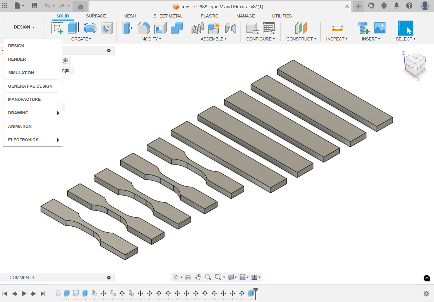
Figure 1. Fusion program - design vs. manufacture.
Step 2: Under the MANAGE tab in toolbar, click on the Tool Library to open the tool library window. Please see Figure 2 for reference.
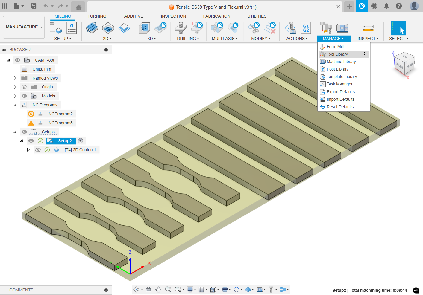
Figure 2. Tool library location.
Step 3: Under the Local tab, right-click on the Library and select Import Libraries. Select the downloaded Maker Store Fusion360 Tool Library V1.2.tools file and hit Open. Please see Figure 3 for reference.
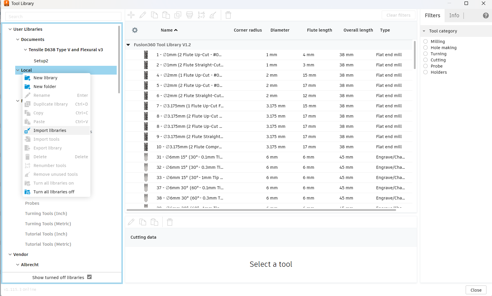
Figure 3. Importing a tool library.
Step 4: The Maker Store Fusion360 Tool Library will appear as shown in Figure 4. Click on Close.
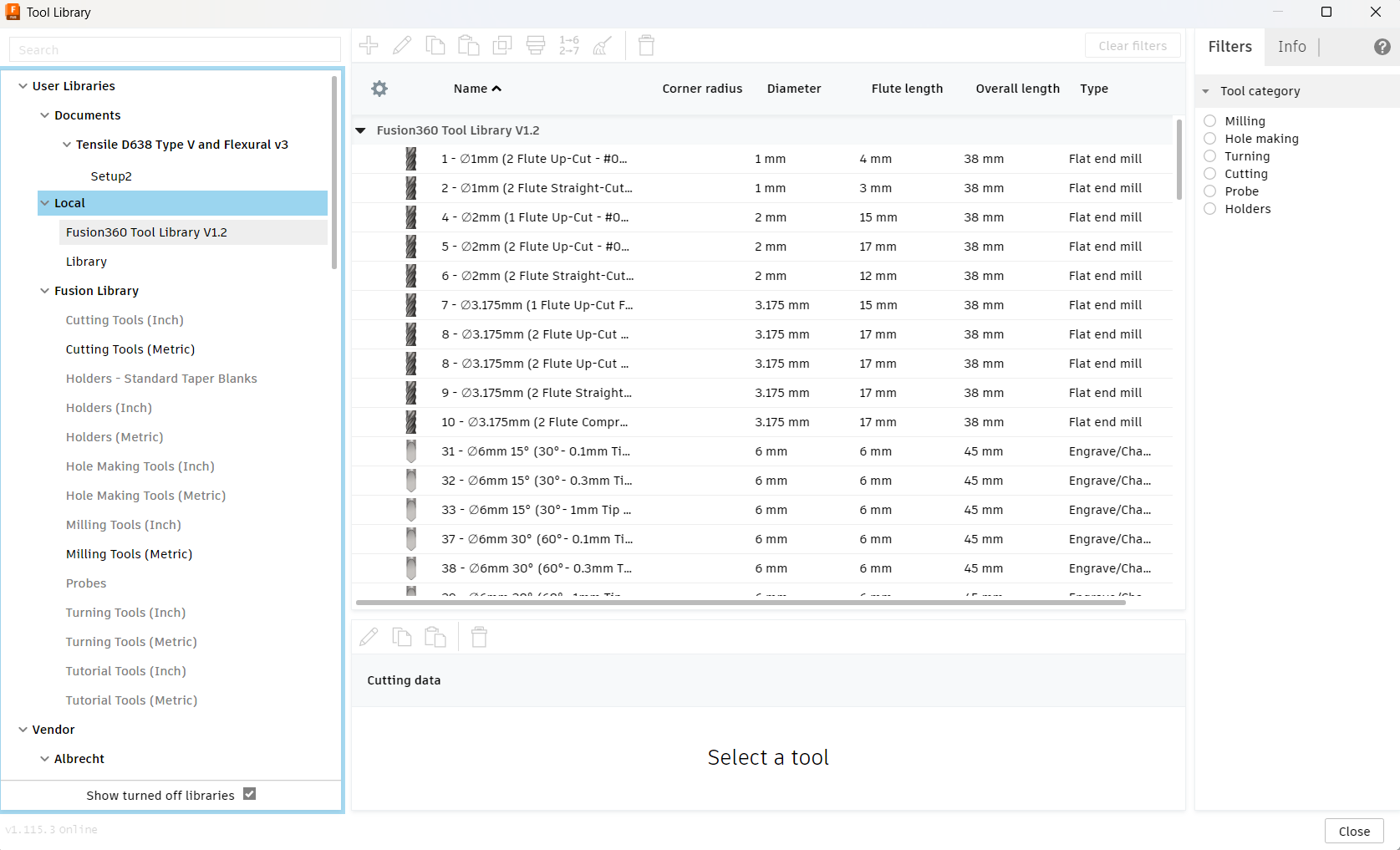
Figure 4. Local tool library.
Same steps should be repeated to import the Various suppliers tool library, available in the Documents folder.
¶ Importing Maker Store Fusion 360 Post-Processor
Step 1: Under the ACTIONS tab on the toolbar, click on Post Process. On the Post drop-down menu, click on Choose from library. See Figures 5 and 6 for reference.
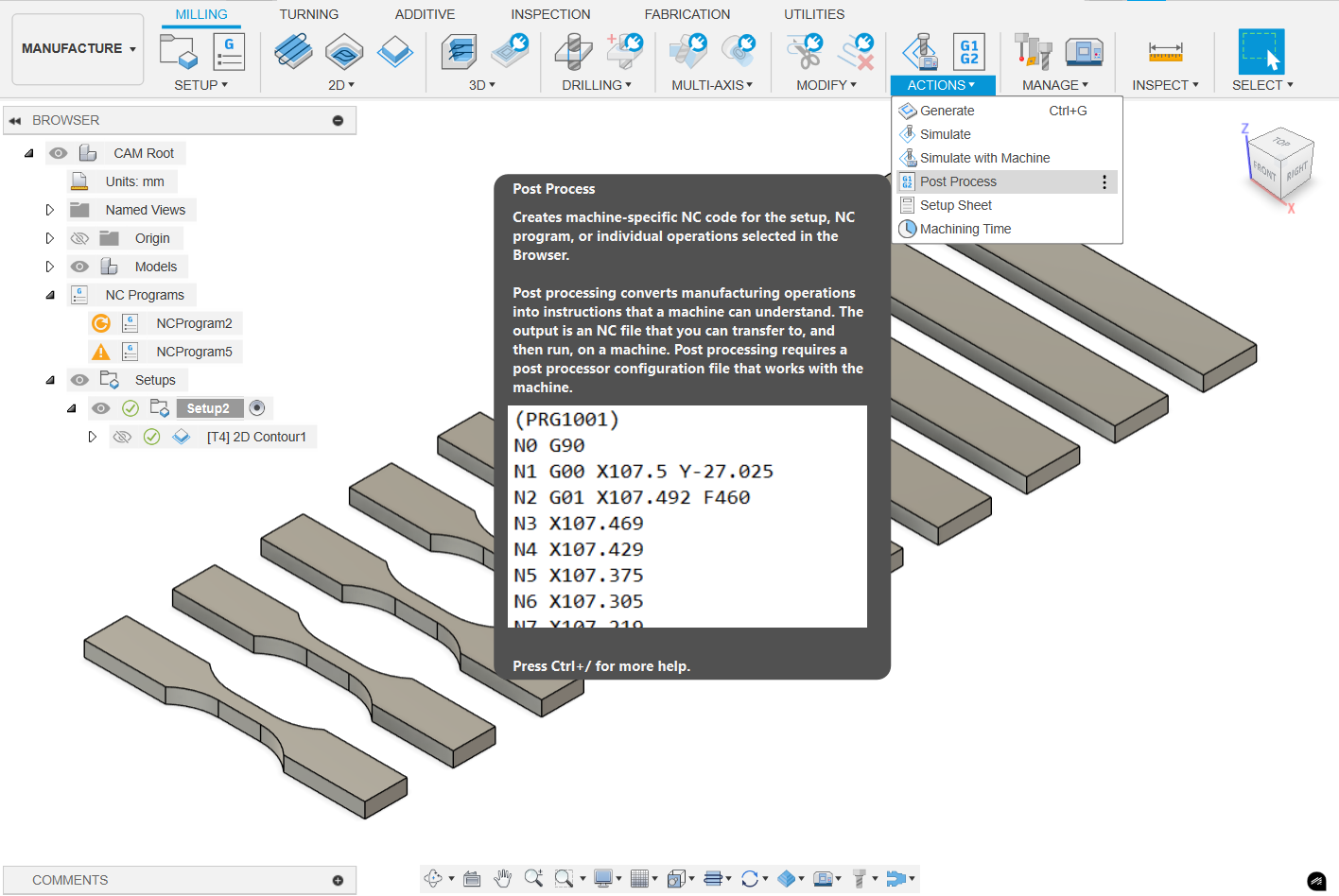
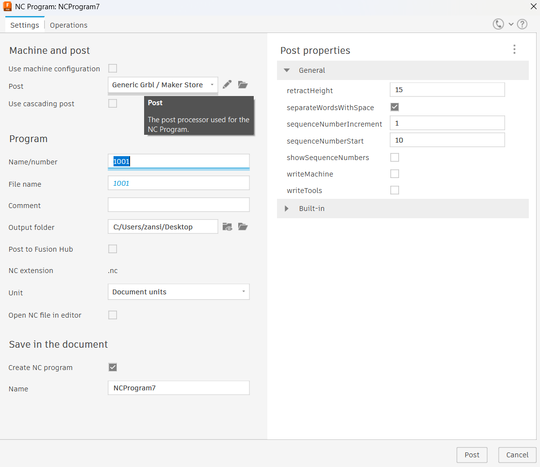
Figures 5 and 6. Post processor for CAM.
Step 2: Click on the Import button, (see Figure 7), and select the downloaded Maker Store Fusion360 Post Processor.cps file.
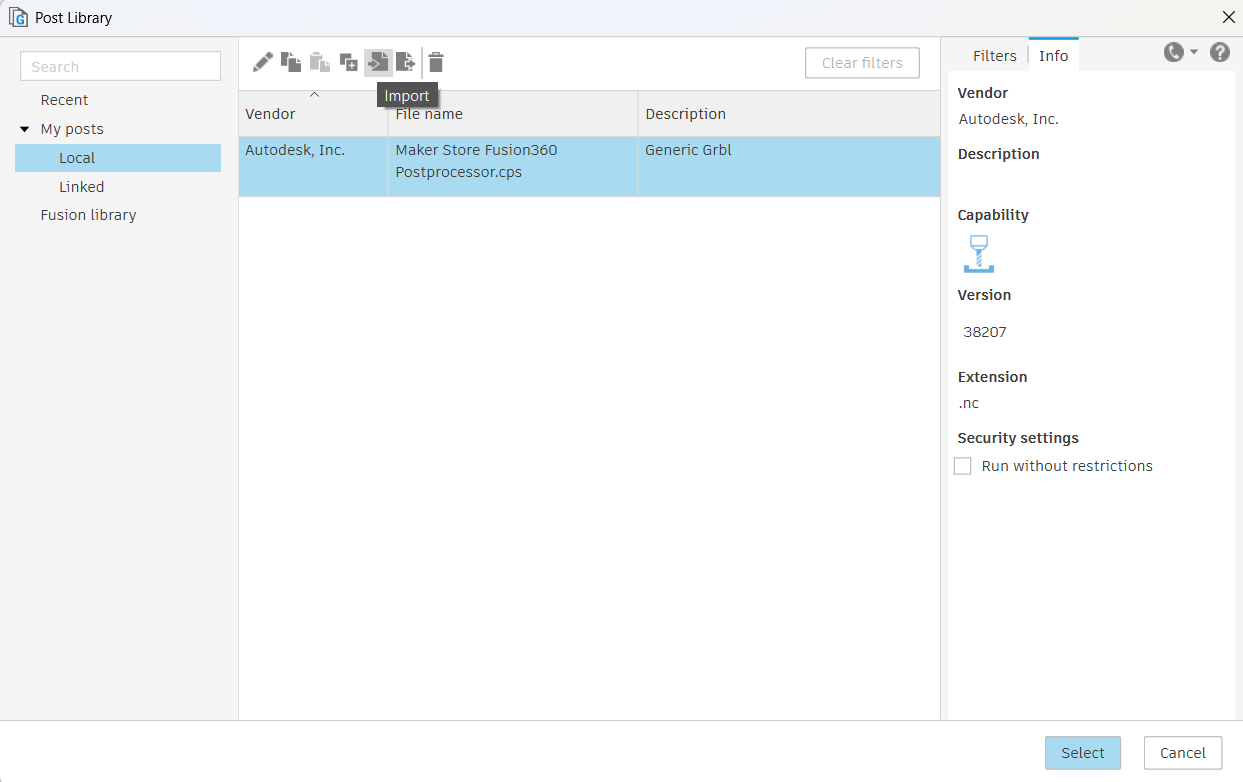
Figure 7. Local postprocessor import.
Step 3: Select the newly imported post processor and click Select. The new post processor has been successfully imported and selected to be used with your project.
Close the post-processor window.
Congratulations, you have successfully imported the Fusion 360 Post-Processor!
¶ Creating Toolpaths
Step 1: Under the SETUP tab on the toolbar, select New Setup. A setup window will open, under the Operation Type select Milling. In the orientation menu, select the correct orientation in which your tool will travel (i.e., make the X, Y and Z directions match in real life and in software). The Setup process enables you to configure your workpiece in the software.
As a general rule, X-Axis should be directed towards the right, Y-Axis forward, and the Z-Axis up.
Step 2: Under the Stock tab, change Stock Offset Mode to No Additional Stock.
Step 3: Under the Setup tab, change Origin to Stock box point. Make sure the bottom left corner is selected as the stock point. This will act as the zero point for the machining. After that, click OK. See Figure 8.
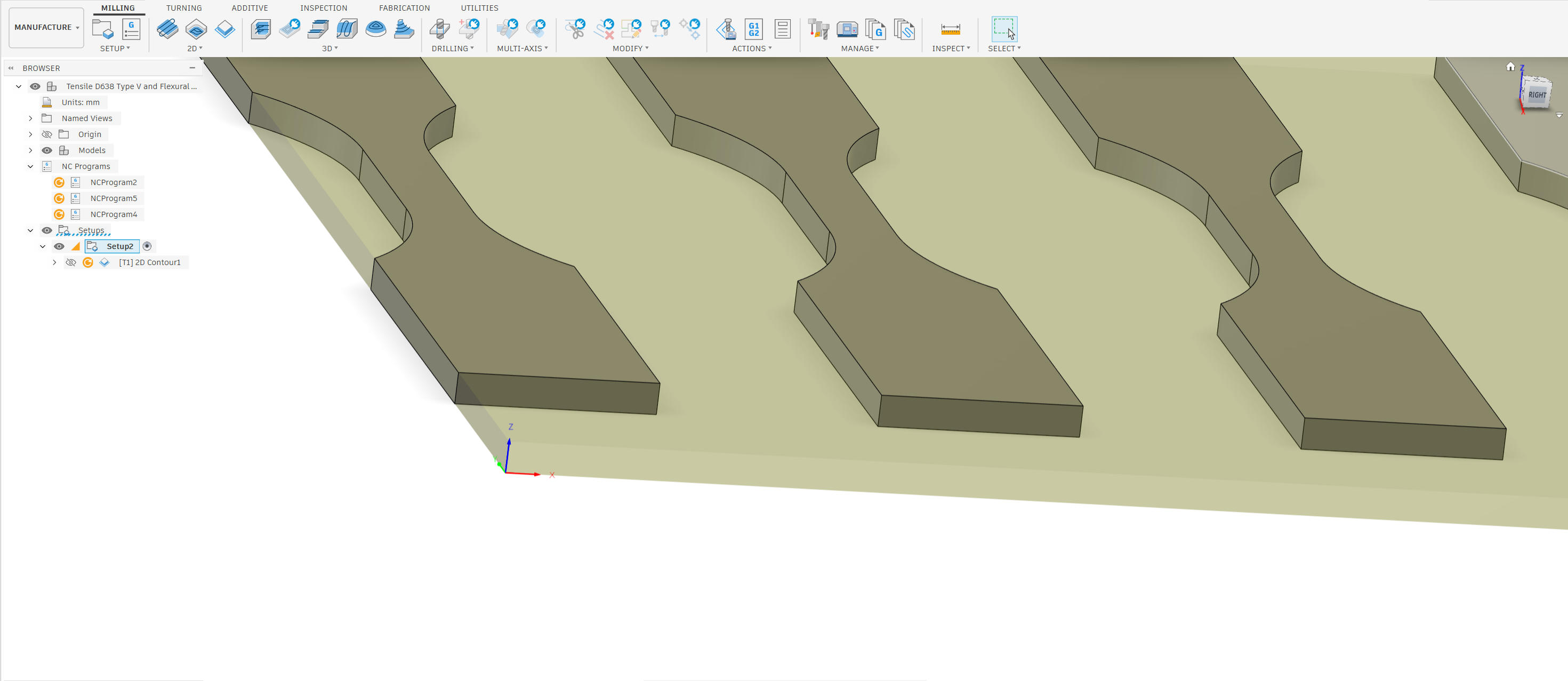
Figure 8. Selecting stock point / zero point.
¶ Basics of Creating a CNC Toolpath
Creating a CNC toolpath is essential for machining parts accurately and efficiently. This guide will explain the different types of operations you can perform with your CNC machine, including 2D, 3D, engraving, contouring, and pocketing.
¶ 1. 2D Toolpath Operations
2D toolpath operations are used for machining flat shapes and designs on a single plane. These operations are typically used for cutting profiles, shapes, and outlines.
¶ Key Features:
- Simple Geometry: Works with basic shapes like circles, squares, and polygons.
- Common Uses: Ideal for cutting out parts, creating signs, and making templates.
¶ Example:
- Cutting a square or circular shape from a sheet of material.
¶ 2. 3D Toolpath Operations
3D toolpath operations allow for machining complex shapes and surfaces that have depth and curvature. These operations are essential for creating detailed parts and intricate designs.
¶ Key Features:
- Complex Geometry: Handles curves, slopes, and varying depths.
- Common Uses: Suitable for sculpting, creating molds, and detailed artistic designs.
¶ Example:
- Machining a 3D model of a sculpture or a complex part with varying heights.
¶ 3. Engraving Operations
Engraving operations are used to create text, logos, or intricate designs on the surface of a material. This operation typically involves shallow cuts to produce detailed markings.
¶ Key Features:
- Shallow Depth: Engraving usually requires a small depth of cut.
- Common Uses: Ideal for adding branding, serial numbers, or decorative elements.
¶ Example:
- Engraving a company logo onto a wooden plaque.
¶ 4. Contouring Operations
Contouring operations involve following the outline of a shape or profile. This operation is often used to create the final shape of a part by cutting along its edges.
¶ Key Features:
- Edge Following: The toolpath follows the contour of the design.
- Common Uses: Used for finishing edges and creating precise outlines.
¶ Example:
- Cutting the outer profile of a part after roughing operations.
¶ 5. Pocketing Operations
Pocketing operations are used to remove material from a defined area, creating a recess or pocket in the workpiece. This operation is essential for creating features like cavities or slots.
¶ Key Features:
- Material Removal: Involves removing material from within a defined boundary.
- Common Uses: Suitable for creating pockets for assembly, weight reduction, or aesthetic purposes.
¶ Example:
- Creating a pocket in a part to house a component or to reduce weight.
Below is an example of how to set up only one of the operations (Contouring). Otjers such as pocketing or engraving have different workflows.
¶ Contouring
Step 1: Under the 2D tab, click on 2D Contour. The Contour operation will be used to follow the outline of a shape or profile. Under the Tool tab click on the Maker Store Fusion 360 Tool Library and select the bit number being used (e.g. #004 (Ø2mm 1F Upcut)). This is a 1 flute, uncoated carbide end mill with a 2mm cut diameter and 1/8 inch shank diameter that is specifically designed for plastics. Click on Select.
Step 2: Under the Coolant tab, select Disabled. Set the Spindle Speed and Cutting Feedrate. For example,you can use Spindle Speed = 18000 rpm and Cutting Feedrate = 1000mm/min. Set the Ramp and Plunge Feedrate = 750mm/min. Ensure you match the feeds and speeds correctly to the material being cut and end mill used. FEEDS AND SPEEDS CALCULATORS available online. AI is decent at recommendations too.
Step 3: Click on the Geometry tab right next to the Tool tab and select the shape profile. The selection will be displayed under Contour Selection. Click OK. See Figure 9.
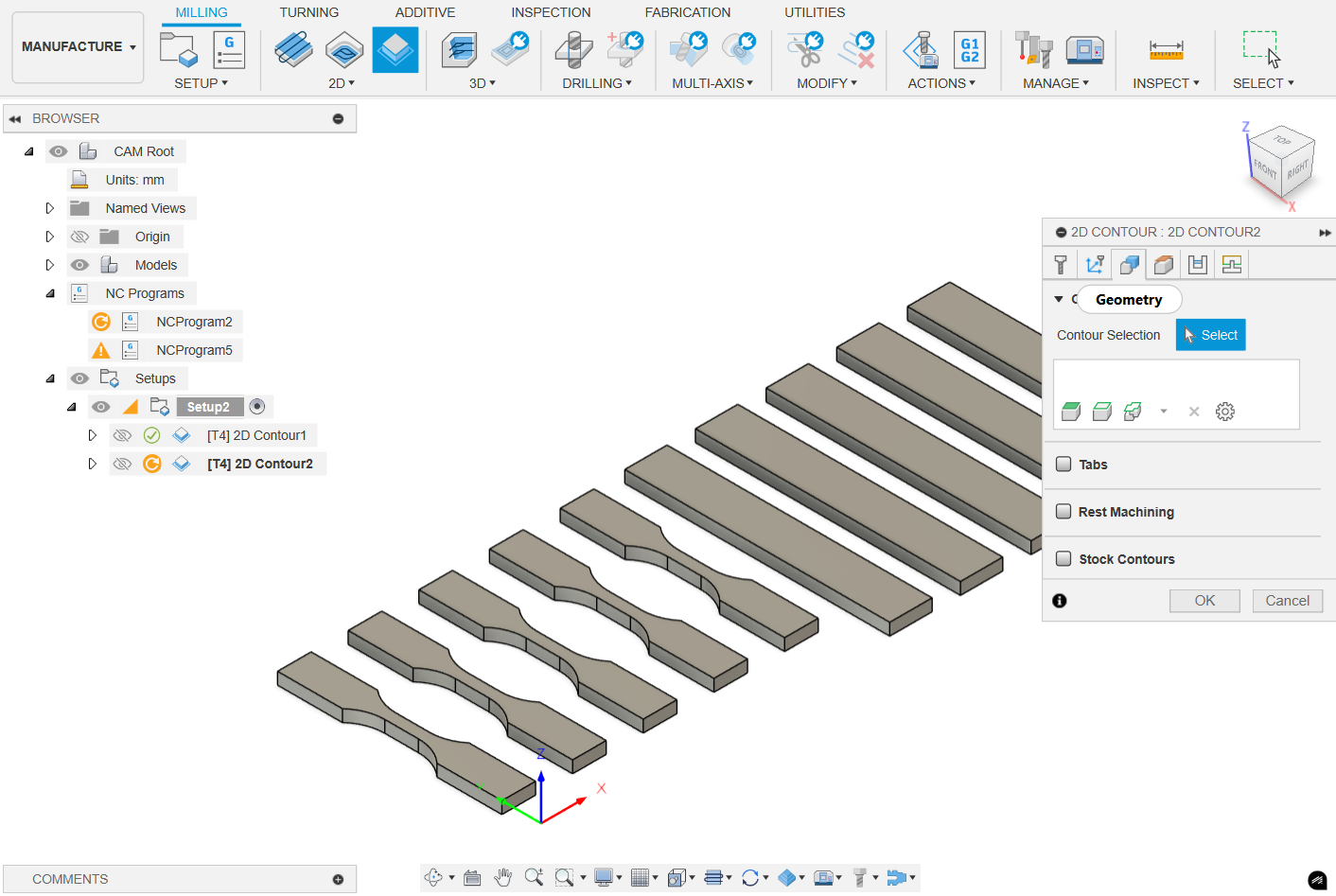
Figure 9. 2D Contour setup.
Step 4: Click on the Heights tab. Ensure the Heights are set properly to avoid clamps during movement and start ramping slowly before the end mill reaches the top of the material. Click OK.
Step 5: Left-click on the Passes tab. Uncheck the Roughing Passes. Select the Multiple Depths section. Under this section, enter the Maximum Roughing Stepdown = 0.25mm or 0.50mm, and ensure the Use Even Stepdowns is checked. Also check the Feed Optimization.
Note: The Stock to Leave parameter is used so that the leftover material can be removed in a finishing pass. This finishing pass provides a better finish. However, for most of our milling this is not needed.
Step 6: The configured operation will be displayed in the CAM environment under the Setup tree. To view the simulation of the operation, right-click on it, and select Simulate. Click on the play (▷) button. The simulation will show you how the tool (end mill) will machine the part. After viewing the simulation, click on Exit Simulation. See Figure 10.
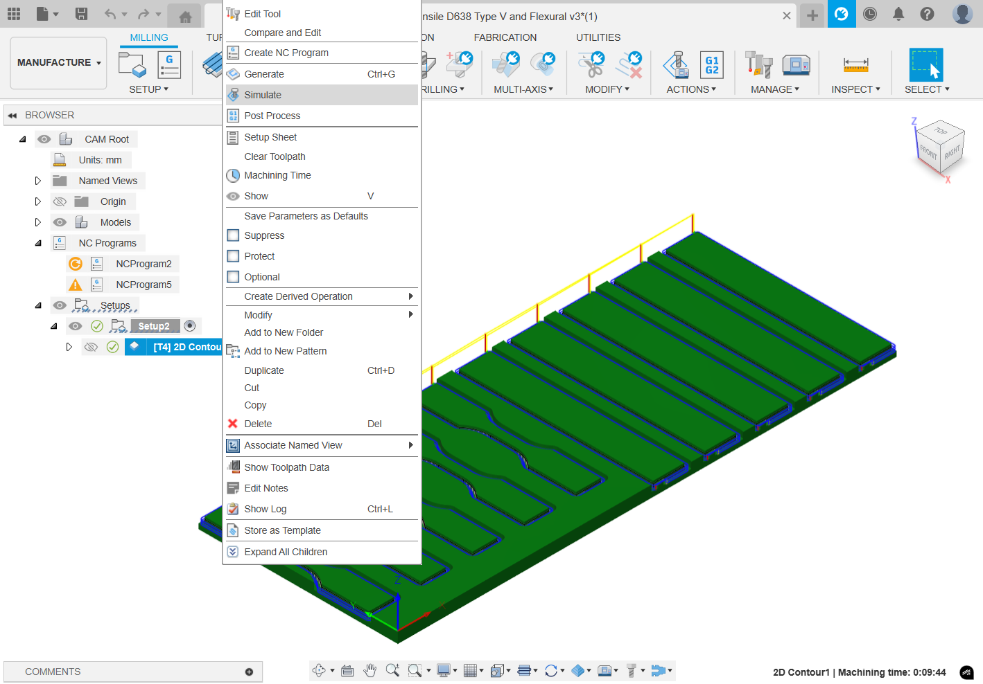
Figure 10. Simulation of tool paths.
Step 7: Left-click on the Linking tab next to the Passes tab and under the Ramp section, select Ramp Type as Plunge and enter Ramp Clearance Height = 0.1mm. Enter Ramp Clearance Height = 0.1mm. Under Positions you can define exit and entry points into the material. It is preferable to start and stop the milling operations away from the gauge length of specimens.
Step 8: Tabs should be added to the model. Tabs are the extra material pieces left on the workpiece that keep it clamped and prevent it from becoming a projectile during the final pass of the last operation. After the machining has been completed, the tabs can be easily removed with a Stanley knife.
If automatic tabs are sufficient instead of manual placement, left-click on the Geometry tab and select the lower profile of the rectangle on the model. This selection will be displayed as Closed Section 1 in the Contour Selection. Next, check the Tabs tab and change Tab Positioning to # Number of tabs. Enter Tabs per Contour required. If manual tabs are preferred, choose the edges under Manual tabs.
Step 9: (optional) If roughing/stock to leave was used, the same operation can be performed again with the exact same settings, but with the Stock to Leave unchecked this time. This is called a Finishing pass to provide a better finish.
¶ Post Processing
The final phase in generating the toolpaths is post-processing, which involves using the Post Processor downloaded earlier to create toolpaths/G-codes.
Every specific operation such as engraving, pocketing, etc will have a separate toolpath.
Step 1: In the MANUFACTURE environment, under Setup right-click on operation and select Post Process. In the Post tab ensure Maker Store Fusion360 Post Processor, which was imported earlier, is selected. Under Program, enter the Name/number, such as “{Your Initials} Tensile Contouring – 188”. This naming convention will help in the easy identification of the operation and the end mill # required for the operation. Under the Output folder, select the destination of this G-Code file to be saved. Click on Post. See Figure 11.
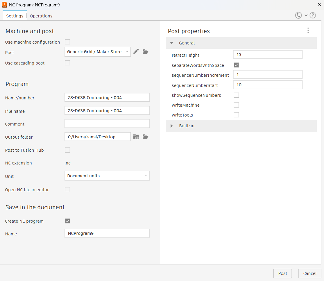
Figure 11. Exporting gcode (.nc file).
If there is multiple operations to be performed, such as pocketing and contouring, an efficient workflow needs to be considered. Deciding the order of operations is essential - for example to prevent cutting the parts away from the stock material prior to pocketing and sending them flying. Do not forget to add tabs!